Project: Golf Ball Trajectory with 3D Computer Vision and 6 DoF Kinematics
A hardware-software system for high-speed tracking and plotting the trajectory of a golf ball in 3D space during putting.

Summary
What: Developed a hardware-software system for tracking and plotting the trajectory of a golf ball in 3D space during putting. We used two industrial high speed cameras in a stereoscopic setup with MATLAB for back and frontend programming.
Why: In golf putting, the accuracy of a putt is highly dependent by how quickly the ball reaches pure roll (non-slip condition) after it is putted. The less a ball slips, the less it will deviate from its desired straight path. In order to design putters that minimize slip, our sponsor required a measurement system to quantify the effectiveness of their putter prototypes.
When: Senior design project (2016).
Who: I was lead hardware developer and programmer working with 3 project members.
Putter and ball markers are captured by a high speed camera, the marker movements are converted to object trajectory and velocity, then plotted in a GUI
The Project
Hardware
Computer vision is not the only way to track ball trajectory. For example, a radar setup is used in baseball stadiums. We ultimately down-selected on using a high-speed computer vision system with stereoscopic setup because it can precisely track both trajectory and rotation.
When scoping out a high speed camera, there are a few important metrics to consider:
- Cost - does it fit within your budget
- Compatibility - does it have GigE vision or use some other standard
- Framerate - does it have enough framerate for your application
- Image quality - does it have enough resolution for your FoV
- Stereoscopy - does it support stereoscopic vision (usually one master camera communicates with one slave camera)
- All-in-one - is the camera system an all-in-one package (or does it require a separate frame-grabber)
Use the right lens, camera, and lighting setup
- This means avoiding optical distortion (no wide-angle or fisheye lens) and sometimes using a telecentric lens for small FoV, high precision applications.
- Don't prioritize aperture, because you can make up for low aperture with controlled lighting conditions to illuminate your object of interest.
- While a low depth of field lens is great for photography, make sure the depth of field fits within the variation in working distance for your industrial application.
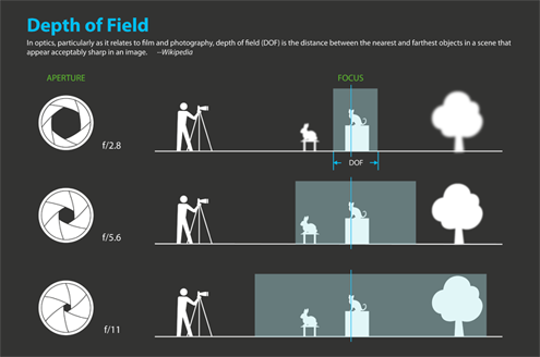
- In high speed vision, your light needs to be bright and usually from an LED source. Low frequency lighting will result in unwanted strobing effects.
- If you don't need color, don't buy color.
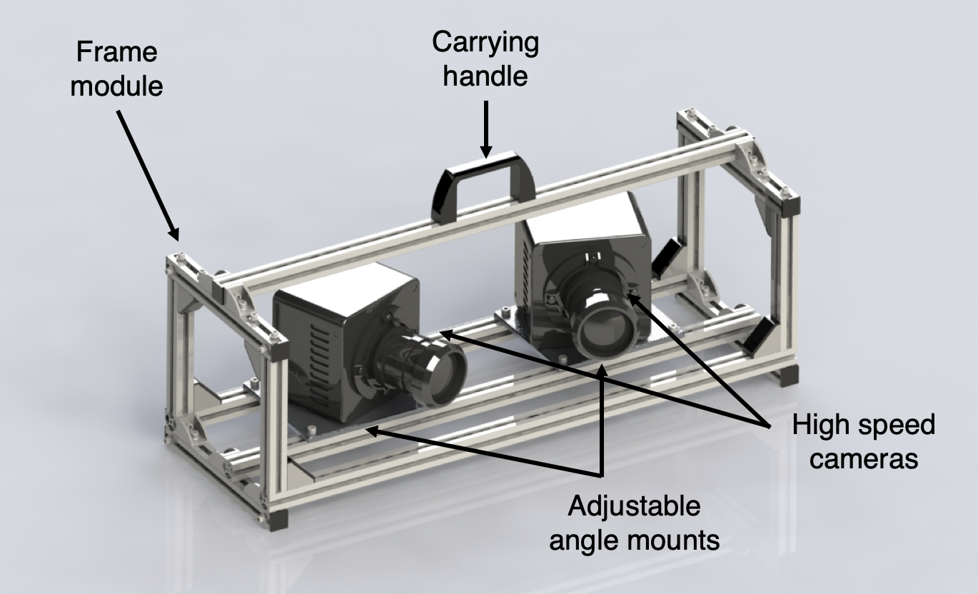
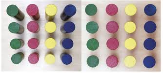
We used a pair of Photron Mini UX50 cameras, which ended up fitting nicely within our $50k budget. These are 1080p, color cameras that shoot up to 2500 FPS. We chose color because we wanted the option to use different colored dots for cases with high side-spin, where a dot may rotate onto the other side of the ball and become obscured.
We placed 3 markers each on the putter and ball, which is the minimum amount needed to track an object's trajectory and orientation (robotic terms: translation and rotation).
We also made a quick hardware setup to house the unit and printed a calibration pattern.
Computer Vision
We converted a real scene into a matrix of points and their locations at each timestep. There are three key steps:
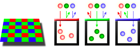
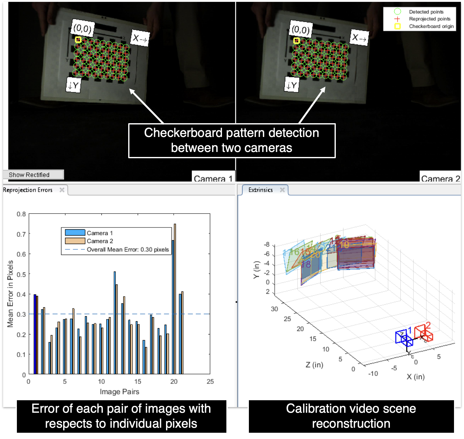
- Calibrate the cameras in the scene with a checkerboard pattern
- Use object detection to track the location of each marker during the duration of the putt
- Put the marker location data into a 4x3xt matrix (X, Y, Z, and timestamp of three markers, for t frames)
This is the part where using a GigE vision enabled camera is important. MATLAB has vision libraries which allowed us to integrate pre-made calibration code into our application. MATLAB also has libraries with functions for object detection in the Computer Vision Toolbox.
Scene Reconstruction and Roll Characteristics
Now the matrix of marker coordinates need to be converted into useful numbers that show the balls trajectory and orientation. There are three key steps in doing this:
- The ball calculation program uses dot tracking data obtained by the tracking code to create a barycentric coordinate system of the ball for each timeframe.
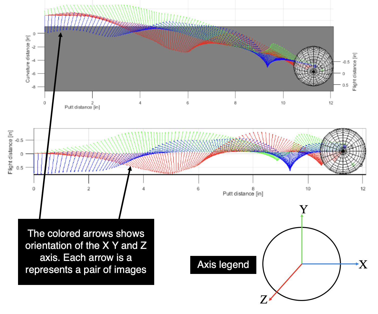
- An affine transformation between the coordinate systems are calculated and applied to a Cartesian frame represented by a homogeneous 4x4 matrix which includes a 3x3 matrix containing the ball’s direction cosines and a 3x1 matrix containing the ball’s center point location. The 4x4 transformation matrix is a concept used in robotics to describe the translation and rotation of a joint.
- From this, we extract the ball’s rotation, change in roll, pitch, and yaw (RPY), and the ball’s translation, change in x, y, and z directions, in Euclidian space.
The ball calculation module allows the system to approximate the ball’s location and orientation at each timeframe, which allows it to extract important data such as the ball’s linear and angular velocity curves, distance to pure roll, and launch angle. The module also plots an animated simulation of the ball’s trajectory for easily understandable data visualization.
GUI
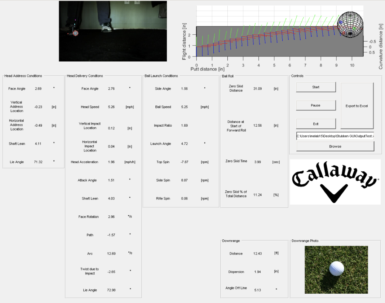
In order to create a friendly interface between the system’s user and the system itself, the project required multiple custom graphic user interfaces (GUIs). Initially, the system runs off of the Photron PFV software GUI in order to record footage.
Custom GUIs come into place when the video footage is imported into MATLAB. One initial GUI was developed to allow the user to discern which type of test is being run, and is shown in the figure below. It gives the user an option to select between an indoor or outdoor putt and a human or putter robot test. The reason for developing this GUI is that it allows for different parts of the code to be examined for different tests. For example, an outdoor test does not account for downrange data (once that code is developed), so there’s no point in running through that part of the code during outdoor tests.